Compression strut system
Adjustable compression struts with a central tubular section and a threaded fork end and pin connection at each end, in carbon steel and stainless steel.
M12 to M100 carbon · M12 to M56 stainless
Compression strut system
Design Principles
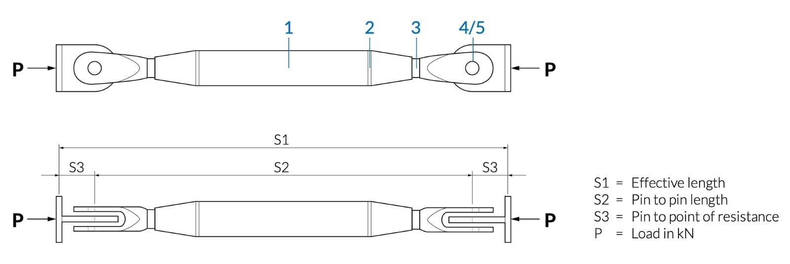
A compression strut comprises a central tubular section with a threaded taper connection welded at each end.
The taper connection is assembled with a threaded fork/pin end connection and threaded lock cover. The threaded fork end connection enables the compression strut to be adjusted in length. The nominal strut adjustment length is +/- 50 mm.
The tapered lock cover and machined cone conceal the threads.
The installed compression strut is fixed to the final length by use of a grub screw set into the cone.
The strut system is designed in accordance with EN1993-1-1 and EN1993 -1-8 and their respective UK National Annexes. The ultimate capacities quoted take account of self-weight bending of the strut in accordance with equation 6.10, Table NA.A1.2(B) UK National Annex to EN1990.
Critical Sections
1 CHS verification
- Section capacity (combined bending & axial)
2 Interface between CHS & welded cone
- Weld size required
3 Threaded bar
- Combined bending & axial
- Axial resistance of thread
4Fork
- Combined bending & axial
5 Pin
- Combined bending & shear
NB: Reference to ‘bending’ above means the summation of strut buckling and self-weight bending effects.
All material factors are as the UK National Annex.