
Product Data
A variety of fittings are available for the DST520 system and your tie bar requirements.
All fittings and components are designed to exceed the load capacity of the bar.
These details are also available as a 2D or 3D download.
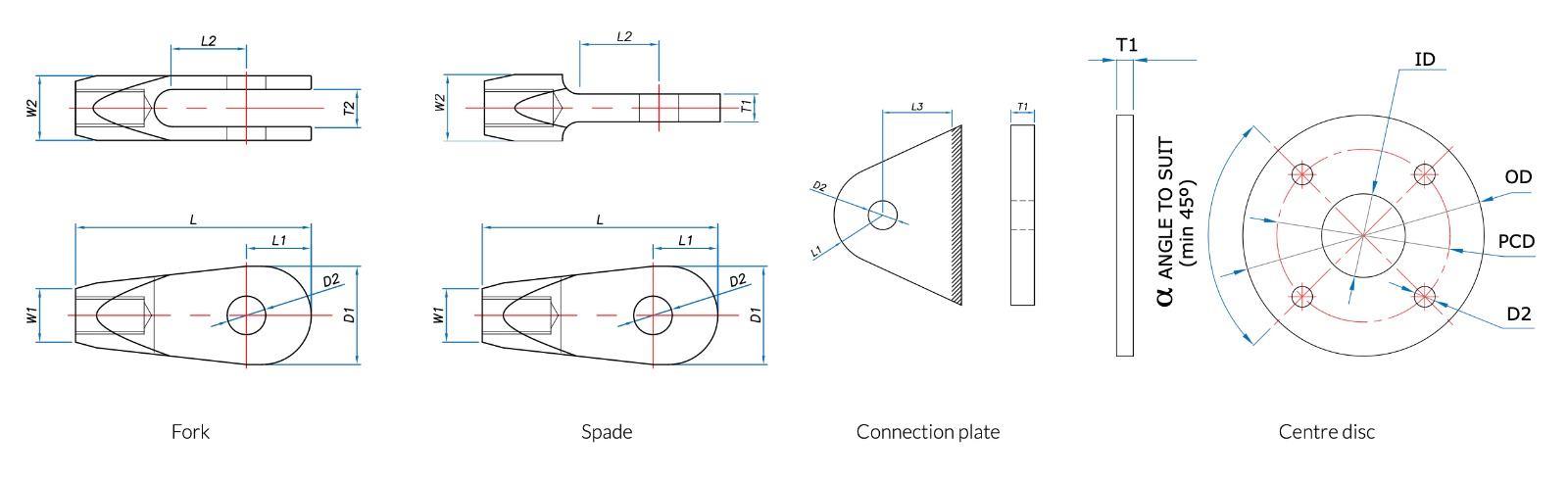
T5 Fork and Spade Dimensions
| M12 | M16 | M20 | M24 | M30 | M36 | M42 | M48 | M56 | M64 | M76 | M90 | M100 | |||
|---|---|---|---|---|---|---|---|---|---|---|---|---|---|---|---|
| Fork length | Lf | 90 | 112 | 132 | 155 | 189 | 217 | 243 | 266 | 313 | 348 | 420 | 498 | 575 | |
| Spade length | Ls | 90 | 112 | 132 | 155 | 189 | 217 | 243 | 266 | 313 | 373 | 445 | 523 | 600 | |
| Diameter | W1 | 18 | 22 | 29 | 35 | 43 | 52 | 60 | 68 | 80 | 91 | 108 | 129 | 143 | |
| Thickness | W2 | 24 | 28 | 35 | 42 | 52 | 64 | 74 | 84 | 95 | 120 | 148 | 170 | 181 | |
| Jaw gap (fork only) +0/-2mm |
T2 | 14 | 16 | 19 | 24 | 30 | 36 | 39 | 44 | 49 | 59 | 76 | 86 | 91 | |
| Spade thickness | T1 | 10 | 12 | 15 | 20 | 25 | 30 | 35 | 40 | 45 | 55 | 70 | 80 | 85 | |
| Width | D1 | 32 | 43 | 51 | 62 | 79 | 93 | 107 | 121 | 145 | 167 | 199 | 246 | 287 | |
| Pin hole diameter | D2 | 13 | 17 | 21 | 25 | 31 | 37 | 43 | 50 | 58 | 66 | 78 | 96 | 111 | |
| Projection | L1 | 21 | 27 | 33 | 41 | 52 | 61 | 69 | 78 | 96 | 110 | 131 | 161 | 188 | |
| Jaw depth (fork) | L2 | 25 | 30 | 42 | 50 | 59 | 68 | 70 | 87 | 105 | 120 | 141 | 171 | 198 |
All dimensions in mm.
T6 Accessories
|
Connection Plates |
M12 | M16 | M20 | M24 | M30 | M36 | M42 | M48 | M56 | M64 | M76 | M90 | M100 | |
|---|---|---|---|---|---|---|---|---|---|---|---|---|---|---|
| Thickness | T1 | 10 | 12 | 15 | 20 | 25 | 30 | 35 | 40 | 45 | 55 | 70 | 80 | 85 |
| Pin hole diameter | D2 | 13 | 17 | 21 | 25 | 31 | 37 | 43 | 49 | 57 | 65 | 78 | 96 | 111 |
| Projection | L1 | 21 | 27 | 33 | 41 | 52 | 61 | 69 | 78 | 96 | 110 | 131 | 161 | 188 |
| Clearance | L3 | 32 | 38 | 52 | 62 | 74 | 87 | 97 | 107 | 125 | 140 | 161 | 196 | 222 |
| Grade plate to BS EN 10025 | S355 | S355 | S355 | S355 | S355 | S355 | S355 | S355 | S355 | S355 | S355 | S355 | S355 |
Ensure clearance for paint/galvanising
| Centre Discs | Name | M12 | M16 | M20 | M24 | M30 | M36 | M42 | M48 | M56 |
|---|---|---|---|---|---|---|---|---|---|---|
| Thickness | T1 | 10 | 12 | 15 | 20 | 25 | 30 | 35 | 40 | 45 |
| Overall diameter | OD | 145 | 185 | 245 | 285 | 350 | 420 | 490 | 560 | 660 |
| Centre hole | ID | 50 | 60 | 70 | 90 | 100 | 120 | 140 | 160 | 200 |
| Pin hole diameter | D2 | 13 | 17 | 21 | 25 | 31 | 37 | 43 | 49 | 57 |
| PCD | PCD | 110 | 140 | 180 | 210 | 260 | 310 | 360 | 410 | 480 |
| Grade plate to BS EN 10025 | S355 | S355 | S355 | S355 | S355 | S355 | S355 | S355 | S355 |
All dimensions in mm. Ensure clearance for paint/galvanising. For stainless steel connection plates or centre discs, marine grade stainless with a minimum tensile strength of S355 must be used.
T7 Accessories
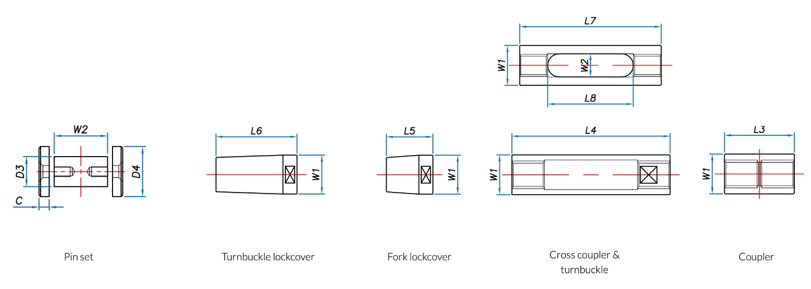
| Pinsets | M12 | M16 | M20 | M24 | M30 | M36 | M42 | M48 | M56 | M64 | M76 | M85 | M90 | M100 | |
|---|---|---|---|---|---|---|---|---|---|---|---|---|---|---|---|
| Pin Diameter | D3 | 12 | 16 | 20 | 24 | 30 | 36 | 42 | 48 | 56 | 64 | 76 | 94 | 94 | 109 |
| Pin body length | W2 | 24 | 28 | 36 | 43 | 53 | 65 | 75 | 86 | 96 | 121 | 153 | 173 | 173 | 183 |
| End cap diameter | D4 | 20 | 25 | 32 | 35 | 50 | 55 | 60 | 60 | 70 | 86 | 100 | 120 | 120 | 140 |
| End cap thickness | C | 3 | 5 | 6 | 6 | 10 | 10 | 12 | 12 | 12 | 14 | 15 | 20 | 20 | 20 |
| Lockcovers | M12 | M16 | M20 | M24 | M30 | M36 | M42 | M48 | M56 | M64 | M76 | M85 | M90 | M100 | |
|---|---|---|---|---|---|---|---|---|---|---|---|---|---|---|---|
| Lockcover diameter | W1 | 18 | 22 | 29 | 35 | 43 | 52 | 60 | 68 | 80 | 91 | 108 | 129 | 129 | 143 |
| Fork lockcover length | L5 | 25 | 26 | 40 | 45 | 50 | 55 | 60 | 60 | 75 | 85 | 91 | 126 | 126 | 134 |
| Turnbuckle lockcover length | L6 | 30 | 33 | 78 | 84 | 87 | 93 | 102 | 105 | 106 | 112 | 118 | 153 | 153 | 160 |
|
Turnbuckles/Couplers |
M12 | M16 | M20 | M24 | M30 | M36 | M42 | M48 | M56 | M64 | M76 | M85 | M90 | M100 | |
|---|---|---|---|---|---|---|---|---|---|---|---|---|---|---|---|
| Coupler length | L3 | 37 | 45 | 53 | 64 | 75 | 89 | 100 | 115 | 135 | 145 | 165 | 195 | 195 | 215 |
| Coupler/turnbuckle diameter | W1 | 18 | 22 | 29 | 35 | 43 | 52 | 60 | 68 | 80 | 91 | 108 | 129 | 129 | 143 |
| Turnbuckle length | L4 | 70 | 85 | 144 | 155 | 170 | 180 | 195 | 210 | 230 | 240 | 268 | 290 | 290 | 315 |
All dimensions in mm.
Alternative Tendon Arrangements:
These are our standard range of fittings.
We can manufacture special central and end connection details to your specific design and construction requirements.
For example : special machined forks, spade end couplings, special pins, plate connections, cross couplers and fabricated brackets.
Please contact us to discuss your specific requirements.